Huge flow numbers may be impressive, but optimizing airflow at mid-valve lift is key to power.
If airflow though a valve port is plotted on a graph for the entire valve cycle (from opening to peak lift and back to close), the area under the curve is total airflow, which corresponds to total power. So if you can fatten the curve on both sides of peak lift in the low to mid-range area rather than just raising the maximum peak, you end up with more total area under the curve and more usable power.
Air velocity is affected by not only the cross-sectional area and volume of the intake port but also by the short turn radius of the intake port just above the intake valve. If the curvature of the radius is too sharp for the volume of air the port is trying to flow at high rpm, airflow starts to separate from the short side radius. This restricts airflow and hurts potential power.
So for high rpm power, you want a wider curve on the short side radius. On the other hand, if you’re porting a head for a street motor, you want good airflow and velocity at low rpm so a sharp radius works better for that kind of application.
Keeping the cross-sectional area of the intake port consistent up to the point where the short side radius starts is recommended for best airflow. Sudden changes in port area can cause the air to speed up or slow down. The port volume also has to be matched to the engine size and rpm. A small block Chevy V8 head with 180cc port volume would be a good street head, but you would want larger ports for a high revving race engine.
Raising the port location in the cylinder head helps straighten out and improve airflow too. Many aftermarket heads feature raised ports for this reason. But if you go with raised port heads or raise the port location by porting the casting, you also have to make sure the new port location lines up with the ports in the intake manifold.
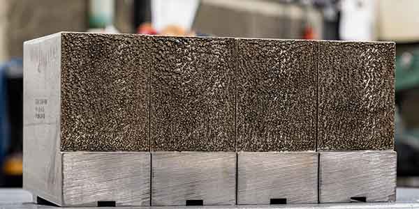
One way to visualize a port configuration is to make a 3D cast of the port. By pouring rubber compound into the port and letting it cure, you can then pry out the mold casting to better see what the port actually looks like. Or, you can take the high tech approach and digitally map the port with a 3D pinpoint plotting devise and import the data into a CAD/CAM software for further analysis and visualization.
Wet Flow Testing
How the air flows through the ports can also affect fuel distribution and mixing. A traditional flow bench doesn’t really tell you anything about what’s happening to the air/fuel mixture as it passes through the ports and enters the combustion chamber. Manufacturers often design a certain amount of swirl into the intake ports to improve air/fuel mixing for emissions and fuel economy. Swirl can also make power but only if it swirls the incoming air/fuel mixture in a beneficial way.
Wet flow testing can reveal things about port flow that are totally invisible with ordinary flow testing. Mixing a fluid that contains UV dye with the air as it enters the port simulates what happens to the air/fuel mixture as it enters the combustion chamber. Viewing the chamber from underneath, you can often see the liquid puddling or streaking as a result of turbulence and misdirected swirl. Playing around with the port configuration can often reduce the puddling and separation that results in a loss of potential power.
In the old days before flow benches were invented to measure airflow, heads were ported manually with a die grinder. A lot of trial-and-error experimentation was required to find out what made an engine run better on the track and what didn’t. Some changes in port configuration were obvious, like blending the port into the bowl area above the valve and matching the ports to the intake and exhaust manifolds. But the benefits of other changes were less obvious, and in some cases actually hurt airflow rather than improve it.
How Valves and Seats Affect Airflow
The size of the valves, the angles on the valves and seats, and the placement of those angles on the valves and seats also has a significant impact on airflow. We’ve covered this topic in other articles so we won’t go too deep into it here. But to summarize the basics, the angles on the intake valves and seats have the most effect on airflow from about .350˝ to .400˝ lift. Beyond .400˝ lift, there is less effect because the opening is so wide.
Multiple angles contour the valve seat and valve face to provide better airflow than a single angle. A typical 3-angle valve job of 30, 45 and 60 degrees may or may not improve flow depending on the head and the application. Airflow can vary from 10 to 30 cfm or more depending on the valve angles alone. According to one well-known head porter, the best flow numbers can be achieved using a special four to seven angle valve seat cutter — not the usual 3-angle cutter that most shops use.
On some performance engines, cutting the intake and exhaust seats to 50 to 55 degrees delivers the best airflow numbers and performance. Locating the valve seat as far out as possible on the valve face not only increases the effective diameter of the opening but also helps cool the valve
better.
Is Porting Necessary?
With so many aftermarket cylinder heads available today with excellent “as cast” ports and CNC machined ports, you can pretty much order just about anything you want – assuming your customer can afford it. On the other hand, if you are looking for a performance edge or are developing a custom application for which no existing heads are available, then doing your own porting may be your only option – that, or sending the heads out to a professional porter to have them reworked.
The latter is recommended if you have little or no porting experience. Better to let somebody who knows what they are doing port the heads than screw up a perfectly good set of heads yourself! A knowledgeable head porter can clean up the bowls, raise the roofs of the intake and exhaust ports and probably find you an extra 30 to 40 horsepower for minimal cost.
Developing a Port Profile
Before flow benches, the only way a head porter could tell if his work improved airflow was if the car ran faster on the track or the engine made more power on a dyno. Today, we have flow benches that can generate and plot all kinds of data. You can compare “before” and “after” numbers to see if you’re going in the right direction or not.
If you’re starting from scratch to develop a new port profile, you grind and test, then grind and test some more, and keep repeating until you are eventually satisfied with the results.
Porting Methods
For light port matching and bowl blending with no significant changes in the cross-sectional area of the ports or the short side radius above the intake valve, you can usually accomplish what you want with a basic hand-held die grinder. Aluminum castings are fairly easy to port, but cast iron is much harder and requires more physical effort and time. You also want a good sharp cutter that will cut quickly and cleanly.
Many head porters will narrow or grind down the valve guide boss that protrudes into the intake port to remove the obstruction. But keep in mind the boss helps support the valve guide, and the shape and location of the boss can have a major impact on how the air/fuel mixture is directed into the combustion chamber.
If you want to increase the port cross-sectional area and volume, you have to be very consistent in how the port is enlarged. The port should have a consistent cross-section and taper gradually toward the short side radius and intake valve. Hand porting a set of cylinder heads takes skill and expertise to achieve consistency. Even then, it’s hard to match the results that can be achieved much more quickly and easily with CNC porting.
With CNC porting, once you have developed the port configuration you want on a flow bench, you can digitally map the port and replicate it again and again with near perfect consistency in the rest of the ports in the cylinder head. And once you have a good port configuration mapped, you can also modify it with CAD/CAM software for different engine applications.
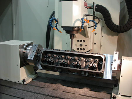
CNC Porting
To port cylinder heads with a CNC machine, you need a machine with 5-axis capability. A 5-axis machine can move the head and tooling to reproduce all of the complex moves it takes to completely machine intake and exhaust ports. Once the CNC machine has been programmed, it is automatic, requires no manual labor other than loading the machine, and is repeatable from one head to the next.
The motions of the tooling are carefully choreographed so that metal is removed in exactly the right places. Figuring out how to program such intricate movements requires a fair amount of CNC know-how as well as software that is up to the job. If you’re new to CNC porting, don’t expect to start porting cylinder heads in the first few weeks after you’ve purchased your equipment. It might be six months to a year before you can CNC port heads confidently.
A port that has been CNC machined usually requires little or no additional finishing. It will often flow just as well as a port that has been smoothed out and finished with a die grinder.
CNC machining unfinished castings is probably the fastest and easiest way to custom port heads. Most aftermarket heads are available with cast ports, CNC machined ports or as raw unfinished castings so you can do your own porting. The problem with trying to modify an existing port is that if the casting is not thick enough, you may grind through a thin spot in the port wall. Besides, most of these heads flow so well out of the box that there’s little additional power to be gained by additional porting.
Of course, sometimes porting may be necessary if a set of heads is being used on an engine with a big stroker crank or a large displacement aftermarket block that needs more airflow. It’s often possible to take a set of aftermarket performance heads that flow 260 to 270 cfm as is out of the box and rework them so they’ll deliver 330 to 340 cfm.
If you are porting a new raw casting, you also have to be concerned about head stability. A green casting that has not yet been thermally cycled on an engine can actually shift around quite a bit. As the metal heats and cools, the head may distort and change the location of guides, seats and decks, which in turn may affect valve sealing and valve life.
A new casting can be stabilized prior to machining it by heating and slow cooling it in an oven, cycling it through a hot parts washer several times, by shaking it at a frequency of 100 Hz to stress relieve the metal, and/or by cryogenically freezing the head. Once the casting has been stabilized, you can machine it and be confident that it will not change.