 Replacement Head I.D. for Ford 6.0L Diesel
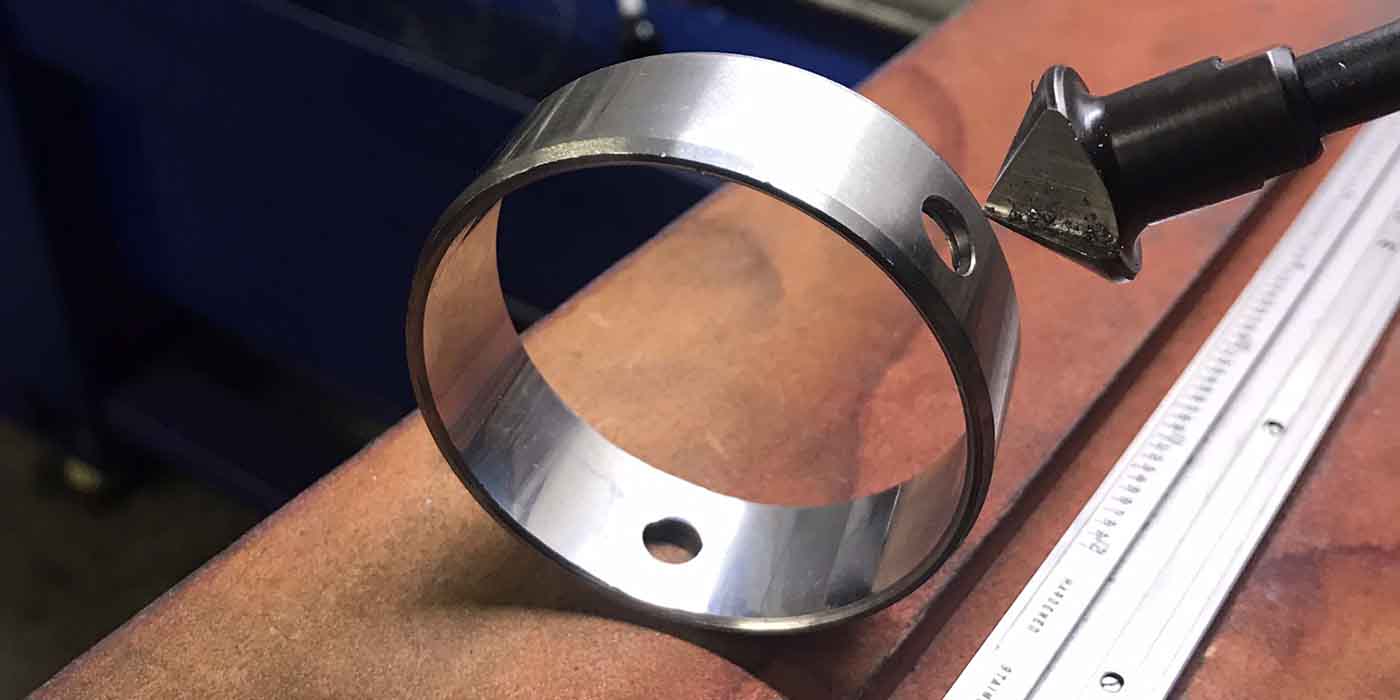
Identifying a Ford 6.0L head by dowel size alone does not necessarily get you the correct replacement cylinder head.
Ford/International have two casting numbers for their 6.0L head, the early 1843080C1 through C4 heads which all have 18mm dowel holes and use an 8mm mounting bolt for the rocker carrier, and the late model or “consolidated” cylinder head casting #1855613C1. It is the #613C1 that can cause confusion.
 This head comes from the factory with EITHER 18mm or 20mm dowel holes and a 10mm rocker arm carrier bolt. The aftermarket 20mm head is the ONLY replacement for this head.
If your head is a #1855613CI casting with 18mm dowel holes, you must use a stepped 18mm to 20mm dowel (FelPro #ES72248) with the aftermarket 20mm head. Failure to use this dowel can result in severe damage to the engine.
Dave Sutton
Sterling Engine Parts
Minneapolis, MN
Keep Chuck Keys in Check
This isn’t the most high-tech Shop Solution in the world, but it can save you hours of lost time and aggravation.
 Have you ever wasted time looking for your drill’s chuck key or fought chucking in a bit with the key tethered or taped to the cord? Here is a solution.
Take a piece of 1/4” heavy walled tubing and cut off about a 2” piece. Then fasten it to the lower handle of the drill or the very top of the cord with a fairly wide tie wrap compressing the tubing a bit.
Then, slip the chuck key into it. It will hold securely out of the way, and you can remove it freely to chuck in a bit without the interference of a cord or tether.
Michael Campiere
Campiere Customs
Chalmette, LA
 ‘Shopping’ Around
One of the best ways to increase business is to make personal contact with your customers. Here is a somewhat different approach.
A machine shop owner in Missouri started a program last year that he calls “Fat Friday.”
Each Friday morning, he drops by the local donut shop and buys one to two 2 dozen assorted cakes. He picks a different garage or fleet and drops by unannounced with the “Fat Friday” food.
He takes the donuts to the owner along with a brochure about his shop and a coupon for a 10% discount on his next purchase. He also makes it a point to carry the goodies through the shop where he uses the opportunity to introduce himself and his machine shop to every employee.
His sales and profits have exceeded his budget thanks to this small investment in time and money.
Steve Rich
Sterling Bearing, Inc.
Kansas City, MO
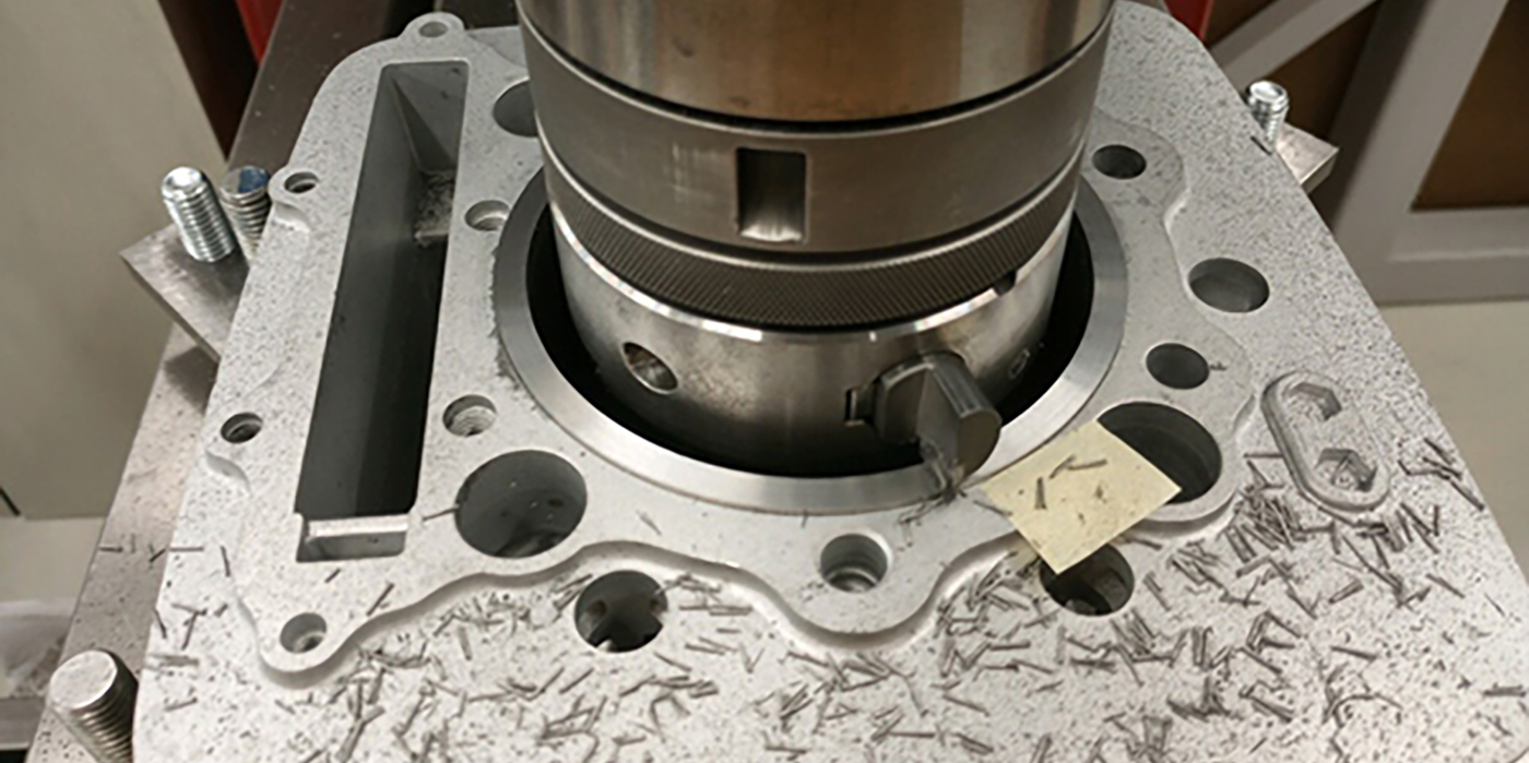
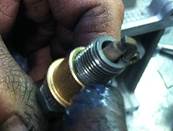
Installation Tool for Spark Plug Repair Inserts
This tool was developed after I got frustrated with supplier installation devices. It is faster, easier and works with most spark plug thread repair inserts, including Perma-Coil, Time-Sert and Heli-Coil.
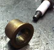
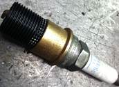
Start with a long reach spark plug, sliding a bronze spacer (metric flange bushing available at your local hardware store) over the plug leaving enough thread to engage the repair insert. (Photo 1). Place a dab of grease on the spacer/flange and thread the insert onto the plug. (Photo 2).
Place a dab of Green Loctite #640 on the OD of the insert. Stick the plug with the insert threaded on it into the spark plug hole (previously tapped to accept the insert).
Tighten the insert into the spark plug hole by simply screwing the spark plug into the hole. (Photo 3). Once it is seated, give a sharp counterclockwise “tap” to your wrench or driver. The insert will stay in place, and you can wind the spark plug bushing back out. The repair is finished.
Dan Morrison
Morrison Auto Machine
Glendale, AZ
Changes in Ring Design
Not all that long ago, what many of us knew about OEM domestic piston ring technology was that a premium ring set was a combination of 5/64” – 5/64” – 3/16” with a cast iron moly top ring, a cast second ring and three piece steel chrome rail oil rings.
More recently, piston ring design has been going through revolutionary changes. This design revolution will continue due to many factors, including government mandated emission reduction and higher fuel mileage requirements, plus various energy policies and energy prices.
These factors also force changes to be made in fuels and lubricants, increasing the challenge faced by piston ring engineers to create a piston ring that works in today’s engines.
Here are some of the changes and challenges we are seeing or can look forward to in piston ring design:
• TOP RING: Rings are moving towards the top of the piston.
– Results in more air/fuel mixture being burned.
– Increases ring temperature and the risk of micro-welding. (Aluminum from piston can melt and stick to the ring bottom side face).
– Materials and Coatings
– OEM material for automotive now steel (no cast or ductile iron).
– OEM Heavy Duty Diesel material is hardened ductile iron, steel, or nitrided stainless steel.
– OEM coatings mostly moly with some nitride.
– Aftermarket trending from cast iron to ductile iron and steel.
– Aftermarket trending from non-coated cast iron to chrome and especially moly coatings.
• SECOND RING: Napier design will become more prevalent. This design results in better oil scraping allowing for lower tension oil rings.
– Larger ring gap opening to manage ring combustion pressure which minimizes gas pressure below the top ring.
– Materials and Coatings
– OEM is trending toward hardened cast iron.
– Aftermarket in general trending away from cast iron, although ductile option for racing showing interest.
• OIL RING: Trend to lower tension for less drag, more horsepower.
– Materials and Coatings
– OEM automotive considering two-piece steel, but this is a very high cost option.
– OEM heavy duty diesel trending to two-piece nitrided steel.
– Aftermarket still very strong on three-piece style with chrome rails, although options for nitride are available.
• ALL RINGS: Rings are becoming thinner and more shallow.
– This improves conformability to the cylinder wall resulting in better sealing and less oil consumption. Also less drag and more power.
Engine Pro Technical Committee, with thanks to Hastings Piston Ring Co.